
| 일 | 월 | 화 | 수 | 목 | 금 | 토 |
|---|---|---|---|---|---|---|
| 1 | 2 | 3 | ||||
| 4 | 5 | 6 | 7 | 8 | 9 | 10 |
| 11 | 12 | 13 | 14 | 15 | 16 | 17 |
| 18 | 19 | 20 | 21 | 22 | 23 | 24 |
| 25 | 26 | 27 | 28 | 29 | 30 | 31 |
- 이메일 영어
- abaqus
- 아바쿠스
- Heat transfer analysis
- FEBiO
- plot3
- send email
- Tensile test
- contact
- Biphasic
- 접촉해석
- vector angle
- finite element analysis
- 이메일영어
- FEA
- C
- FEBio tutorial
- plot vector
- MATLAB
- 컨택해석
- 영어표현
- Vibration
- Steady state heat transfer
- transform
- Rigid body
- Multi-step loading
- Today
- Total
Enjoy Learning & Knowing
FEBio Tutorial 6: A multi-step analysis 본문
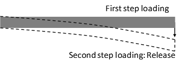
The model for this tutorial is using a beam bending case. The loading for the beam bending has two steps: the first step is applying a static load and the second step is releasing the load of the first step. The results will show the dynamic response of the beam after releasing the applied static load.
Creating a geometry
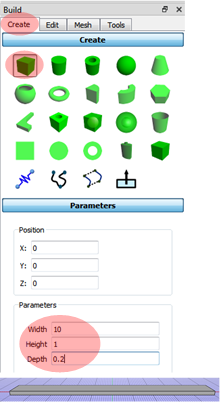
Click Create and select the Box in the Build panel.
Defining the parameters: width 10, height 1, Depth 0.2.
Applying the analysis steps
The initial step at the Steps is a default step to collect all the constraints (bounary conditions, loads, contact interfaces etc.). It is remaining active during all steps wihtout user interruption. If there is an additioanl step with constraint, the constraint is only remaining during the the additionally defined step.
Need three steps
The first step is the Initial from the default setting. It keeps the defined boundary conditions and constraints.
The second step is the quasi-static analysis for the static loading.
The third step is the dynamic anaysis to show the response after releasing the static loading. The beam will be vibrating.
In this tutorial,
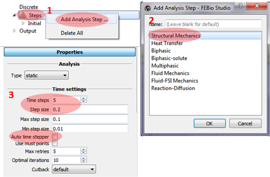
Defining the static load only for the first step.
1. Click Steps at the Model panel and select Add Analysis Step.
2. Select Structral Mechanics.
3. Adding parameters for Time settings: Time steps = 5, Step size = 0.2, and unselect Auto time stepper.
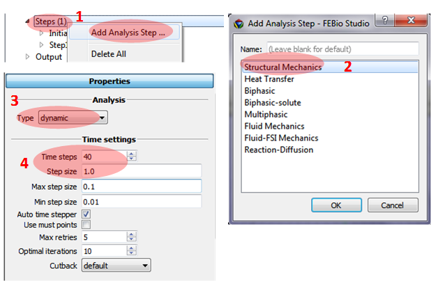
Defining the second step to release the static loading applied for the first step.
1. Click Steps at the Model panel and select Add Analysis Step.
2. Select Structral Mechanics.
3. the second step is dynamic analsyis, so select dynamic at the type of Analysis.
4. Adding parameters for Time settings: Time steps = 40 and Step size = 1.0.
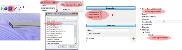
Setting up the boundary conditions
Applying the boundary condition for the initial step. The left end of the beam will be fixed.
1. Click the Face selection button at the top Toolbox bar. Select the left end face of the beam.
2. Click Boundary conditions/Add Boundary Condition at the Model panel and select Fixed displacement.
3. Applying x, y, and z constraints.
4. Can see Fixed displacement boundary condition under the initial step.
The applied boundary condition at the first step will be remaining during all steps.
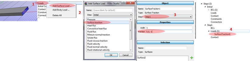
Applying the loading condition.
1. Select the right end of the beam.
2. Click Loads/Add Surface Load and select Select traction.
3. Select Step1 and applying 0, 0, -1 for traction.
4. Can see Surface Traction load at the Step 1.
The Surface traction is a constant traction to a surface, i.e. a constant force per unit area not depending on the nodal number on the surface.
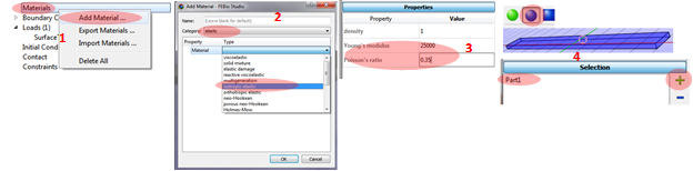
Defining material parameters
1. Click Materials/Add Material.
2. Select elastic Category and isotropic elastic Material.
3. Applying parameters: Young’s modulus = 25000 and Poisson ratio = 0.35.
4. Click Part selection toolbox and select the beam to add it to the Selection.
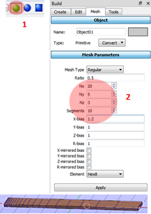
Creating the mesh
1. Click the Object selection toolbox and select the beam.
2. Applying Mesh Parameters: Nx = 20, Ny = 5, Nz = 3, X-bias = 1.2.
X-bias to add more refined mesh at the right end of beam (see below image) due to the higher stress at the fixed boundary condition.
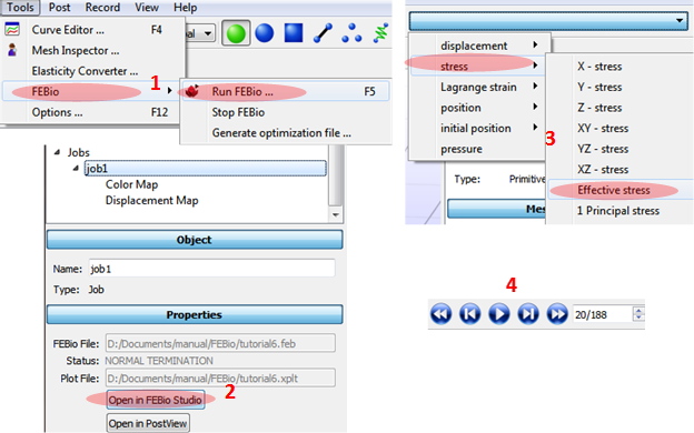
Running the simulation
1. Click FEBio/Run FEBio at the main menu bar.
2. Click Open in FEBio studio after selecting job at the Model panel.
3. Select output at the right top: stress/Effective stress.
4. Play animation.
'FEBio' 카테고리의 다른 글
| FEBio Tutorial7: Heat Transfer Analysis (1) | 2020.04.29 |
|---|---|
| FEBio Tutorial 5: Biphasic unconfined compression (0) | 2020.04.21 |
| FEBio Tutorial 4: The billet problem (0) | 2020.04.15 |
| FEBio Tutorial 3: Twisted bar problem (0) | 2020.04.14 |
| FEBio Tutorial 2: Tensile Test (0) | 2020.04.10 |


