
| 일 | 월 | 화 | 수 | 목 | 금 | 토 |
|---|---|---|---|---|---|---|
| 1 | 2 | 3 | 4 | 5 | 6 | 7 |
| 8 | 9 | 10 | 11 | 12 | 13 | 14 |
| 15 | 16 | 17 | 18 | 19 | 20 | 21 |
| 22 | 23 | 24 | 25 | 26 | 27 | 28 |
| 29 | 30 | 31 |
- 이메일영어
- FEA
- plot vector
- Rigid body
- C
- contact
- abaqus
- 아바쿠스
- Heat transfer analysis
- 컨택해석
- Tensile test
- vector angle
- transform
- send email
- Vibration
- FEBiO
- finite element analysis
- 이메일 영어
- 영어표현
- Multi-step loading
- plot3
- Biphasic
- MATLAB
- 접촉해석
- Steady state heat transfer
- FEBio tutorial
- Today
- Total
Enjoy Learning & Knowing
FEBio Tutorial 3: Twisted bar problem 본문
The model has two boxes. The box on the left side is a deformable body and the box on the right side is a rigid body. They will be connected together.

Creating geometries.
Creating the first box from the Create panel. Click the Box icon and assign position (0, 0, 0) and parameters (4, 1, 1).
Creating the second box. Click the Box icon and assign position (2.5, 0, 0) and parameters (1, 1, 1).
The position is based on the center location of an object.

Selecting surfaces to attach two bodies.
Hiding the second box. Select Object2 from the Model view. Mouse right-click and select Hide the second box.

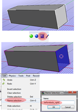
Rotating the first box to show the right side surface.
Change Selecting toolbox for surface selection.
Selecting the right side surface of the first box.
Click the Edit at the Menu bar and select Named selection. Defining a name for the selected surface.
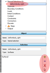
The Named selection is showing at the Model view. As described in Tutorial 1 and 2, we can modify (add or remove) the surfaces from the Menu bar.
Unhide the second box: select the Object2 from the Model view and Mouse right-click and select Show.

Setting up the boundary conditions.
The boundary condition for the left surface of the first box
1. Add Boundary condition at the Model viewer.
2. Select Fixed displacement.
3. Apply a fixed constraint in x, y, and z direction.
4-6. Rotating the model. Select the left surface of the first box and add it to the Selection.

Add a Rigid body to the model.
1. Select Materials at the Model viewer. Right-click and click the Add Material.
2. From the window of Add Material click the Category and select other.
Select Rigid body from Type.
3. It will show a diamond shape marker (the center of rotation of an object) which is located at the origin.
4. In order to place the center of rotation at the second box, apply a new Center of mass at the Properties window (2.5, 0, 0.5). The diamond shape marker moves to the center of the second box.

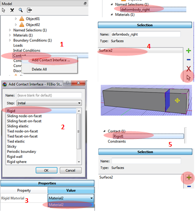
Rigid interface connection between the deformable body and the rigid body.
1. Select Contact at the Main viewer. Click the right mouse button and select Add Contact Interface.
2. Select Rigid from the window of Add Contact Interface.
3. In the properties window select material value using a defined material before.
Now need to select surface using the Named Selection.
4. Go to the Named Selection at the Model viewer. Select the surface and click the selection arrow. It will show the highlighted surface of the model.
5. Go back to the Contact/Rigid and click Add (+) at the Selection window.
Constraining the rigid body.
1. Select Constraint and add Rigid Constraint.
2. In the window select Fixed rigid displacement/rotation
3. Apply properties: all degree of freedom are constraint except x-rotation.

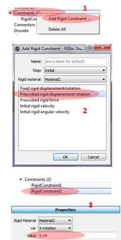
Apply the second constraint for rotation.
1. Select the Constraint/Rigid constraint
2. Select the Prescribed Displacement/Rotation.
3. Select the x-rotation degree of freedom and type 3.14 In the Properties.
Setting up the materials
Assigning materials (Mooney-Rivlin) for the deformable body.
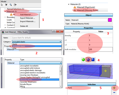
1. Select Materials and Add Material
2. In the Add Material window select uncoupled elastic for the Category and Mooney-Rivlin for the Type.
Mooney-Rivlin materials is created.
3. Typing Properties: density = 1, c1 = 1, c2 = 0, and bulk modulus = 100.
4. Change selection tool as Part selection
5. Select the deformable body and add it in the Selection window.
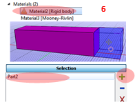
6. Assigning the material of the rigid body. Select Material for the Rigid body and select the second box. Add the selected part to the Selection list.
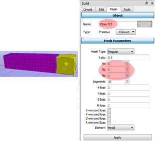
Creating the mesh
1. Click the Mesh in the Build panel.
2. Using the selection toolbox (Object) select the deformable body.
3. Assign the mesh size Nx = 20, Ny = 5, Nz = 5.

Repeat the above step for the second rigid body.
Select the rigid body and apply Nx = 1, Ny = 1, Nz =1.
Now the rigid body and the deformable body are connected even though the node of deformable body and rigid body do not coincide.
Defining the analysis step
Select Steps/Add Analysis Step.
Select Structural Mechanics and see the Stpe1.

Running simulation
This step is the same as Tutorial 2. In the Main menu select Tools/FEBio/Run FEBio.

Post-processing
1. Select the job name and Open FEBio Studio
2. Select stress/Effective stress at the right end of the main menu.
3. Select the last step at the Play bar.

Result figure.

Reference
Tutorial3 from https://help.febio.org/PreView/PreView_2_1/index.html
'FEBio' 카테고리의 다른 글
| FEBio Tutorial 6: A multi-step analysis (0) | 2020.04.28 |
|---|---|
| FEBio Tutorial 5: Biphasic unconfined compression (0) | 2020.04.21 |
| FEBio Tutorial 4: The billet problem (0) | 2020.04.15 |
| FEBio Tutorial 2: Tensile Test (0) | 2020.04.10 |
| FEBio Tutorial 1: Navigating GUI (0) | 2020.04.09 |


